Here are some examples to help supplement this youtube video and get you going with your own CAN based Arduino projects to interface with Megasquirt ECUs.
Video Demo:
https://www.youtube.com/watch?v=S_0LBVyBUl0
I'm going to break it down into two small projects for simplicity. Receiving data over CAN and then transmitting. Obviously you can combine the two and likely will depending on your project.
Can Transceiver:
There are quit a few CAN transceivers available on Amazon and eBay etc. I tried a few and only had luck using this specific type:
You will need the appropriate CAN interface library so your Arduino can talk to the CAN transceiver. Once again I tried many and had the best luck with this one https://github.com/autowp/arduino-mcp2515/tree/master
Arduino Boards:
Arduino boards didn't make a difference. I used a variety so use what you like.
CAN Library:
The CAN interface library came with a few examples of how to use it in general but they did not work for me with the Megasquirt. I'm providing some very simplistic examples below to help get you going. I have interfaced with both MS2 and MS3 based systems.
Code Examples:
I added a small bit of code that changes your values to -999 if you loose CAN data. This is just a simple sanity check so that you can tell broadcast data is no longer been received.
Here's an example receiving CAN transmissions from the Megasquirt.
// CAN receiving
#include <SPI.h>
#include <mcp2515.h>
struct can_frame canMsg;
MCP2515 mcp2515(10); // SPI CS Pin 10
// megasquirt variables
int RPM, TPS, CLT;
// can variables
unsigned long previousMillis=0;
int delayPeriod=1000;
void setup() {
Serial.begin(115200);
mcp2515.reset();
mcp2515.setBitrate(CAN_500KBPS, MCP_8MHZ);
mcp2515.setNormalMode();
Serial.println("Hello MCP2515 Arduino");
}
void loop() {
if (mcp2515.readMessage(&canMsg) == MCP2515::ERROR_OK) {
/*
Serial.print("CanMsg.can_id: ");
Serial.print(canMsg.can_id); // print ID
Serial.print(" ");
Serial.print("CanMsg.can_dlc: ");
Serial.print(canMsg.can_dlc, HEX); // print DLC
Serial.print(" ");
*/
/*
for (int i = 0; i<canMsg.can_dlc; i++) { // print the data
Serial.print(canMsg.data[i],HEX);
Serial.print(" ");
}
Serial.println();
*/
switch (canMsg.can_id) {
case 1512: // dash broadcasting group
RPM = (float)(word(canMsg.data[2], canMsg.data[3]));
CLT = (float)(word(canMsg.data[4], canMsg.data[5])); CLT = (CLT / 10);
TPS = (float)(word(canMsg.data[6], canMsg.data[7])); TPS = (TPS / 10);
break;
}
previousMillis=0; // reset no data timer
}
else { // no CAN bus data coming in
unsigned long currentMillis = millis();
if(previousMillis == 0){
previousMillis = currentMillis; // entered no data timer
}
else if(currentMillis - previousMillis > delayPeriod) { // no data timer expired
previousMillis = currentMillis;
RPM = -999;
CLT = -999;
TPS = -999;
}
}
Serial.print("RPM: ");
Serial.print(RPM);
Serial.print(" CLT: ");
Serial.print(CLT);
Serial.print(" TPS: ");
Serial.println(TPS);
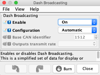
}In order for the above code to receive anything make sure your Megasquirt is broadcasting CAN dash data. You can choose other types of CAN broadcasting inside of Tuner Studio but Dash Broadcasting is easiest. Click on "CAN-bus / Testmodes" in Tuner Studio and then "Dash Broadcasting" and set it like the screen shot below
CAN transmission to Megasquirt
// this feeds data into megasquirt over CAN bus
// pot with +5, GND, signal to A0
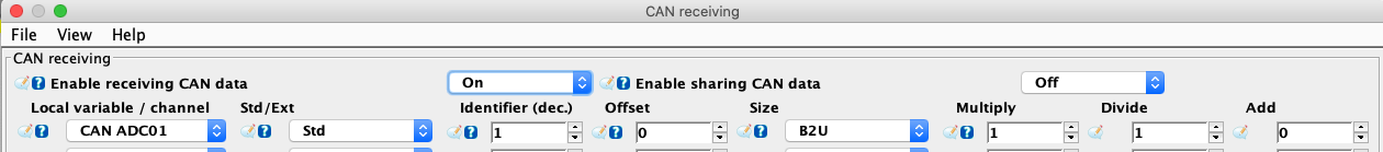
// MS3 setup under "CAN Receiving", "CAN ADC01", Std, identifier = 1, Size = B2U
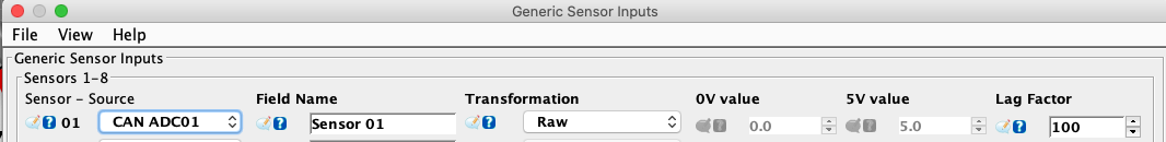
// MS3 under Advanced Engine, "Generic Sensor Inputs", "CAN ADC01", Sensor 01, RAW
// setup gauge to display Sensor 01
#include <SPI.h> //Library for using SPI Communication
#include <mcp2515.h> //Library for using CAN Communication
struct can_frame canMsg;
MCP2515 mcp2515(10);
int sensor01=A0;
int s1, a, b;
void setup()
{
while (!Serial);
Serial.begin(9600);
SPI.begin(); //Begins SPI communication
mcp2515.reset();
mcp2515.setBitrate(CAN_500KBPS,MCP_8MHZ); //Sets CAN at speed 500KBPS and Clock 8MHz
mcp2515.setNormalMode();
}
void loop()
{
s1=analogRead(sensor01);
canMsg.data[0]=s1/256;
b=s1%256;
//a=highByte(s1); alternate way of doing it
//b=lowByte(s1);
canMsg.can_id = 0x001; //CAN id as 0x001 (leading zeros matter on this field)
canMsg.can_dlc = 8; //CAN data length as 8
//canMsg.data[0] = a;
canMsg.data[1] = b;
canMsg.data[2] = 0x00;
canMsg.data[3] = 0x00;
canMsg.data[4] = 0x00;
canMsg.data[5] = 0x00;
canMsg.data[6] = 0x00;
canMsg.data[7] = 0x00;
mcp2515.sendMessage(&canMsg); //Sends the CAN message
delay(10);
}In order to receive data in Tuner Studio you need to setup a few things.
First click on "Advanced Engine" and then "Generic Sensor Inputs". Setup like the screen shot below.
Now go to "CAN-bus / Testmodes" and then "CAN receiving" and setup like the screen shot below.
The next screen shot shows how I setup the gauge for demo purposes just using "Sensor 01" that was setup in the above screen shots.
